The Basics of Conductivity Electrodes
Table of Contents
- What is Conductivity?
- The Importance of Conductivity in Water Quality
- Conductivity and TDS
- Temperature Compensation for Conductivity Measurements
- Calculating Accurate Temperature Compensation
- Conductivity Measurement Methods and Electrode Types
- Contacting Method
- Inductive Method
- Contacting vs Inductive Electrodes
- Conclusion
Helpful Links
What is Conductivity?
Specific conductance, or conductivity, with regards to water quality is the measurement of how many and how mobile ions are in solution. The more ions that are present and the faster they can move, the higher the conductivity. This water quality parameter is measured in Siemens/cm (S/cm), or more commonly microSiemens/cm (µS/cm).
Conductivity is also the inverse of resistivity so one Siemen can be expressed as 1/Ω. This is why it was previously referred to as mhos, or micro-mhos. A ‘mho’ being ‘ohm’ spelled backward
The Importance of Conductivity in Water Quality
As each ion has a different level of conductivity, it cannot be used to determine the specific levels of ions in solution except in extremely controlled environments. Because conductivity provides a general measurement of the presence of ions in water, it is commonly used to monitor pollution levels. For example, the manufacturing of microelectronics, such as semiconductors, require ultrapure water for washing after each phase. Any impurities in the water can react with the materials and result in reduced performance. Because of this, proper quality control requires continuous monitoring of conductivity.
In aquaculture, conductivity is tracked to identify imbalances in the water used, as even small changes impact fish and plant growth.
As another example, the conductivity of groundwater near agricultural centers is monitored closely for the benefit of both the farmers and the environment. Sensors will be placed near the crops so the farmers can be alerted if salinity suddenly changes and action is required to save a field of crops. Additional sensors are also installed in bodies of water surrounding agriculture to monitor the effects of runoff, thereby preventing algal blooms.
Conductivity and Total Dissolved Solids (TDS)
Gravimetric measurement is the most accurate method of measuring TDS, but it requires filtration and evaporation of the liquid to weigh the remaining salts. Many people, myself included, don’t want to lug the required equipment onsite and taking tens or hundreds of samples to map TDS over time. As a result, conductivity sensors are often used to monitor TDS levels in waterways. TDS and conductivity are correlated, but not causally related. TDS includes ions, which conductivity is a direct measure for, but also includes dissolved organic matter, which is often a poor conductor whose concentration is not related to conductivity. When dissolved organic matter is relatively low, then conductivity is a fairly accurate measurement. For most natural water samples, it has been found to be accurate to about ±10%. To achieve a more accurate comparison between conductivity and TDS, it is best to perform one gravimetric measurement of the sample then divide the result by the measured conductivity. This gives a correlation factor, Ke, which is used on future conductivity measurements to get an estimate of TDS. This is an excellent method to use when the concentration of dissolved organic matter is not expected to change. If C = conductivity, this can be expressed as:
The correlation factor ranges between 0.5 and 0.8 and must be determined empirically. If the main ions are not known, a common correlation factor used is 0.67.
Temperature Compensation for Conductivity Measurements
Conductivity increases as temperature increases, which is automatically compensated for by many instruments. This standardizes the output to 25°C to allow for measurement comparison. A problem arises because the amount that conductivity changes per degree is influenced by the composition of the solution. The automatic temperature compensation (ATC) typically used is 2% increase per degree Celsius to standardize each reading to 25 °C, but can introduce errors in measurements of extremely low or high conductivity.
For extremely low conductivity, such as in ultrapure water, each degree Celsius change induce a 5% change in conductivity, whereas extremely concentrated ionic solutions require temperature compensation of only 1.5% per degree Celsius. The 1.5% compensation also applies to certain acidic and alkaline solutions and empirical testing is required to determine the most accurate compensation method for your application.
There are instruments that offer programmable temperature compensation, but that functionality comes with a price. It is relatively easy to compensate for as a consumer by following the equation below if the automatic temperature compensation is known and a different compensation value is desired. Many industrial automation programs such as PLCs will allow for inclusion of these equations to modify the output values to whatever is most suitable for the application.
Below is the equation for manual calculation of temperature compensation along with examples. By knowing the ATC percentage used, it is possible to work backwards in circumstances where a more accurate temperature compensation value is known. This equation can also find the most accurate temperature compensation value in a controlled environment.

Example: pHionics conductivity sensors compensate by 2% and the conductivity output after compensation is 740 µS/cm at 30°C. The solution contains ions that are not as reactive to heat so the measured conductivity value must be determined for use with a more accurate temperature compensation percentage.

Calculating accurate temperature compensation
Example: Through lab experiments, you find that the average conductivity for your application is +763 µS/cm at 25°C and the average conductivity at 30°C is 822 µS/cm . To determine true Temperature Compensation, use the following equation:
Conductivity Measurement Methods and Electrode Types
Conductivity can be measured through either the inductive or contacting method, with the best method being dependent on the range of conductivity, or the aggressiveness of the chemical being measured. The cell constant and the frequency of the AC current (ranging 100-50,000Hz) determine the sensitivity of each electrode. Larger cell constants with higher frequencies are for higher ranges of conductivity and vice versa.
Contacting Method
The method is referred to as contacting because the electrode is directly in contact with the water. In its simplest form, the contacting method uses an electrode with two conductive cells that run an alternating current between them. The current causes ion movement toward the oppositely-charged cell. Contacting electrodes can have a range of 0.02-2,000,000 µS/cm, and are currently the best method for accurate measurement of low conductivity (<200 µS/cm).

Electrode Design
Each cell is typically made of a conductive material such as platinum, titanium, graphite, or stainless steel, and surrounded by an insulating material. The cells are made with a specific surface area and placed a fixed distance apart, depending on the conductivity range being measured. The closer the cells are to each other, the more easily current flows between them, causing an increase in measured conductivity. Designing small cells closer together can be necessary to measure extremely low conductivity, while the opposite is true for higher conductivity.
The calculations to standardize measurements between electrodes with different cell constants are typically done by the sensor or transmitter — so knowing them is not necessary as a user. There are certain products with cell constants that vary slightly due to manufacturing processes. In this case, the manufacturer will note that it is a nominal cell constant, commonly meaning variation by about 20%. Many manufacturers of discrete conductivity probes provide a certified cell constant which is verified in quality control.
For the calculation of the cell constant yourself, please use the equations below:
The cell constant (K) is the relationship between cell distance (D) and cell area (A).

The cell constant is multiplied by the measured conductivity (G) to get specific conductivity (σ), thereby standardizing the output.
If the specific conductivity of a sample is known, then an unmodified measured conductance can be used to obtain the cell constant.

pHionics electrodes are always checked to ensure the cell constant never changes so this work does not fall on the user.
Polarization
One problem that 2-cell electrodes must overcome is the polarization effect. Polarization occurs in high ionic solutions. As large numbers of ions concentrate on the oppositely-charged cell, the ions interact and repel each other, creating resistance.
This polarization effect is why many manufacturers, including pHionics, use 4-cell electrodes. With a 4-cell design, one pair of cells—the ‘drive’ pair–is positioned on the outer edges of the electrode and conducts current from one cell to the other. The second pair—the ‘sense’ pair–measures the voltage between the first pair to check the output voltage matches what is expected. When an excess of ions are present and repelling each other, the resistance affects the voltage and the sensing cells automatically increase voltage until it overcomes the repulsion of the ions.


2-cell vs 4-cell Conductivity Electrode Overview

Inductive Method
Inductive Electrode Design
The inductive method is also known as the toroidal method because it uses two cells, each typically containing a wire wrapped around a ferrite core in a toroidal shape. One of the cells outputs an electric field that induces a current in the other cell. The generated current is proportional to the total conductivity of the solution and is effective in removing the polarization effect. The downside of the inductive method is that the solution must have a high enough level of conductivity to interact with the electric field given off by the cells. Large advances have been made recently in toroidal design that have improved their performance at lower conductivities (<200 µS/cm), but some models still experience reduced accuracy. Always read the manuals thoroughly if considering toroidal electrode for low conductivities, as some manufacturers state 0-2,000,000 µS/cm on their website but note in their manuals that the lower limit is around 200 µS/cm.
The main reason that inductive electrodes are used is because the plastic or epoxy bodies make them ideal for extreme environments. Certain devices can function in temperatures up to 270°C. They also can be designed with different plastics for reduced chemical reactivity for the desired application. The plastic body also prevents the electrode from being fouled by accumulation of dirt or oils to reduce maintenance. The electrode will still require cleaning if the center bore gets clogged, but this is generally not an issue.
Contacting vs Inductive Conductivity Electrode Comparison

Conclusion
Hopefully, this article provided a good summary of what conductivity is, and why we measure it, along with the positives and negatives of different electrode designs. pHionics specializes in 4-cell electrodes because they provide the best value in the widest range of applications. We have designed an exceedingly durable sensor integrated with an isolated, 2-wire, 4-20 mA conductivity transmitter for greater accuracy. Our confidence in the pHionics conductivity transmitter allows us to offer an industry-leading 2-year warranty.
For any questions related to conductivity not answered in this article, please contact us and we will be happy to help!
Suggest an Article or Video Topic!
Recent Articles
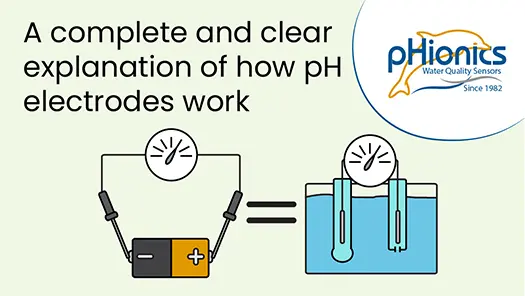
How Glass pH Electrodes Work
In this video, learn about the electrochemistry that allows silver/silver chloride pH electrodes to measure the acidity of solutions. Modern electrode design is also reviewed to demonstrate what improvements have been made and what weaknesses are still present. Click...
STs Series Sensor Storage
STs Series sensors are constructed from high-quality, durable materials that can be stored for long periods of time. The only weak point is the electrode, which can be damaged or expire during storage in the wrong conditions. These conditions vary depending on the type of electrode, which is why we have different storage instructions for each sensor.
How a Glass pH Electrode Works
A comprehensive article covering how glass electrodes measure pH in a simple, understandable format. Specifically for silver/silver chloride electrodes.