How a Glass pH Electrode Works
Introduction
What a pH electode does is quite simple—It measures the difference in hydrogen ions between two solutions. This tells the user how acidic/basic the solution is, which determines how chemicals may react in the solution.
How an electrode performs this measurement is significantly more difficult to understand, but it is worth knowing to ensure proper use in an application. This article provides thorough but easy-to-follow examples showing how a pH electrode works, with the only background information required being a basic understanding of chemistry.

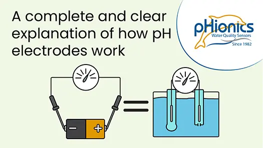
Image 1. Comparison of voltmeter and pH electrode
Voltmeters and pH Electrodes
Just as a voltmeter measures the difference in electron potential between two points in a circuit, pH electrodes measure the difference in hydrogen potential between two solutions. Visually, the two systems may look quite different but, in their basic forms, they are both just two wire leads contacting different points or solutions.
When measuring the voltage of a battery, a lead is placed on the positive and negative ends to form a circuit. This allows a small number of electrons to flow from the point of higher potential energy to the point of lower potential energy, which creates a magnetic field that moves the needle of an analog voltmeter. The magnetic field strength is proportional to the voltage.
Voltmeters can simply measure the voltage that is present in a charged battery. In contrast, two solutions do not normally have potential energy built up between them so a pH electrode must find a way to “charge” the solutions. This is why a pH electrode is not made of just two wires that get placed into a liquid.
To understand how pH electrodes work, we first must go over some basics of electrochemical reactions. If you are already familiar with this subject, then please skip ahead to Creating a pH-Specific Voltage Potential.

Image 2. How a voltmeter works.
Example 1 – Basic Electrochemical Reaction
Image 3 shows the setup of an electrochemical reaction, where two containers with different solutions and metals are connected. Each side is referred to as a half-cell and will be distinguished as either the Left or Right half-cell for the remainder of this example.
Each half-cell holds a piece of metal submerged in solution with a wire running from one piece of metal to the other. A salt bridge containing cations (depicted with “+”) and anions (depicted with “-“) connects the solutions in each half-cell. More on the importance of the salt bridge later.

Image 3. Separated half-cells for electrochemical reaction.
In this particular system, one container has a silver (Ag) plate submerged in a saturated KCl solution. The other container has a platinum (Pt) plate submerged in a solution containing dissolved iron (Fe3+). When electrons are present, the iron accepts an electron, or is reduced, to form Fe2+. Once all available electrons are accepted, then the reaction stops.
When the wire and salt bridge connect the half-cells together, the right half-cell is provided with an additional source of electrons from an oxidation reaction.
The two reactions shown are called half-cell reactions and can be put together to show the full cell reaction.
Since the Standard Cell potential, known as E° cell, is positive, then the reaction is favorable and occurs spontaneously under standard conditions. Standard conditions are 1M concentrations of each aqueous solution with the system at 25°C. When first set up, the pictured system does not have any Fe2+ and the KCl solution is saturated, so conditions are non-standard. Under non-standard conditions, the concentration of reactants and products determines the cell potential and, therefore, how favorable the reaction is.
This is defined mathematically by the simplified Nernst equation shown below:

For this article, the important part of the Nernst equation is understanding the Q value and how it changes. Essentially, a larger ratio of reactants to products lowers the Q value and leads to a higher cell potential, which makes the reaction more favorable. A larger ratio of products to reactants does the opposite, leading to a higher Q and less favorable reaction.
Now, how does that explain what occurs in our setup?
If the system has just been made, then there is fully saturated KCl solution in the left half-cell and there should not be any products (AgCl or Fe2+), so the Q value is low. As such, the reduction reaction is favorable and Fe2+ starts to form by pulling electrons from the Pt plate. This results in a deficit of electrons on the platinum, which causes electron transfer from the other half-cell that can be read by the voltmeter. The transferred electrons are replaced by the oxidation reaction in the left half-cell, while silver chloride is formed as the byproduct. When the chloride ion precipitates to form silver chloride, then the solution is no longer saturated. This allows some of the solid KCl to dissolve and re-saturate the solution.
So the chloride ions precipitate out, but what happens to the dissolved potassium ions?

Image 4. Ion buildup without salt bridge

Image 4. Ion movement with salt bridge.
While K+ is not directly involved in the reaction, an excess of cations in solution would prevent additional KCl from dissolving, leading to an unsaturated solution and higher Q value. To maintain a high cell potential, the salt bridge gives up some of its anions in exchange for K+. In the right half-cell, the opposite occurs as the salt bridge gives up cations in exchange for Fe2+. This is how the salt bridge maintains charge balance, thereby allowing the reaction to continue until an excess of products eventually makes the reaction unfavorable.
Example Two – Creating a pH-Specific Voltage
The previous example provides an understanding of how and why ions flow between half-cells. Now, let’s modify that system to resemble a pH electrode. To do so, we simply make the right side the same as the left side. The new half-cell equations are below:

As the half-cells are the same, there is no electrode potential between them. Instead, the reactions provide a means of one side accepting or giving electrons to the other when acidity differs between them. More on that below.
One other modification to the system is using an ion-selective salt bridge, which is made of a material that only binds hydrogen ions. When this bridge is placed in solution, a thin layer becomes hydrated and exposed oxygen bound to silica (Si) in the bridge also bind H+. More hydrogen ions bind when the salt bridge is in an acidic solution.
Therefore, an ion gradient develops inside the bridge when acidity differs at either end. Sodium present in the bridge is repelled from the area of higher concentration of positive charge to the area of lower concentration.

Image 7. Sodium Ion Concentration Gradient Formation

Image 6. How Ion-Selective Salt Bridges Work
The movement of Na+ leads to an imbalance of charge between the two half-cells. As with the previous example, this imbalance leads to movement of the opposite charge to balance the system. Because the salt bridge only allows for movement of sodium ions, negative ions (electrons, in this example) must move through the wires connecting the half-cells. See Image 8. Electron movement allows for measurement of the voltage, which is proportional to the acidity difference between half-cells. This measurement is then output by the electrode.
That is the basic premise of how pH electrodes work.

Image 8. Ion movement between example 2 half-cells
Please note that the high resistance (50-500 MΩ) of the salt bridge means only a small amount of electrons flow through. This means the reactions involving silver and chloride occur extremely slowly, thereby preserving the life of the system.
Similarities to pH Electrodes
The following diagram compares the Example 2 system with that of a pH electrode.

Image 9. Comparison of exampe half-cells and pH electrode
Electrode 1 is like the Left half-cell in that it also has a wire of silver coated in silver chloride and surrounded by KCl solution, mimicking the piece of silver in the example. A bulb made of a hydrogen-selective salt bridge provides a connection to the outer solution. The main difference is the inner solution, which has a 7.0 pH buffer added for a stable and known half-cell potential (Exact inner solution varies by manufacturer).
Electrode 2 is known as the reference electrode and is most comparable to the Right half-cell. Both have silver/silver chloride submerged in saturated KCl solution (AKA the reference electrolyte). The difference is that the reference electrolyte in the electrode is only exposed to the acidic sample solution by a small junction instead of being mixed. An ideal junction allows the reference solution and sample to contact and complete the circuit while preventing dilution of the reference solution. Unfortunately, all real junctions allow some mixing of the solutions so dilution eventually occurs. As you know, a diluted reference results in a different Q value, thereby affecting the cell potential of the electrode. Whenever the cell potential changes, an electrode becomes inaccurate and must be recalibrated, which is why junctions are the weak point of most electrodes.
Modern Electrode Design
Modern electrodes use various technologies to reduce the dilution problems associated with junctions. Different materials such as wood, ceramic, or Teflon may be used to plug the junction and reduce the flow-through rate. Other methods involve adding a gel to the reference solution to reduce flow. The most effective design sequesters the silver/silver chloride reference wire in a second chamber connected to the first through a junction, as shown in Image 10. This is aptly referred to as a double junction electrode. All double junction electrodes also employ a plug for each junction to further reduce dilution rate.
Most modern electrodes are also combination electrodes, meaning they do not have the separate electrodes shown in the previous examples. Instead, multiple compartments in one cylinder are used to maintain separation of the electrode solutions, as shown in Image 11.

Image 10. Double junction electrode

Image 11. Combination electrode design
Conclusion
In summary, pH electrodes rely on a combination of electrochemical reactions and an ion-selective salt bridge to produce a measurable voltage potential between solutions. While stability remains an issue, modern advancements commonly allow electrodes to function for years without requiring replacement. Newer designs, called differential electrodes, remove the junction and prevent dilution entirely, but that is for another article.
If you are interested in learning more about pH electrodes, please see the following articles:
The Basics of Modern Glass pH Electrodes
For any questions or comments, please reach out using the Contact Us button below. We are always happy to help.
Suggest an Article or Video Topic!
Recent Articles
How Glass pH Electrodes Work
In this video, learn about the electrochemistry that allows silver/silver chloride pH electrodes to measure the acidity of solutions. Modern electrode design is also reviewed to demonstrate what improvements have been made and what weaknesses are still present. Click...
STs Series Sensor Storage
STs Series sensors are constructed from high-quality, durable materials that can be stored for long periods of time. The only weak point is the electrode, which can be damaged or expire during storage in the wrong conditions. These conditions vary depending on the type of electrode, which is why we have different storage instructions for each sensor.

Choose the Right Sensor for Water Quality Monitoring
Sensors are the backbone of any water quality monitoring system since they determine accuracy and reliability. Learn more about important characteristics to consider when choosing a sensor for your application.