Analog Signals: Current vs. Voltage
Before 4-20mA devices, pneumatic systems were the gold standard for analog process control in the early 20th century, using compressed air or unreactive gases to monitor various parameters such as temperature, humidity, tank levels etc. They could transmit signals relatively long distances, were inexpensive for the time, and had low flammability risks. While the pneumatic techniques are still used today for certain applications, electrical analog signaling through current and voltage has become significantly cheaper, more precise, and much quieter.
Components of An Electrical Analog System:
- Power source – The voltage supplier to all electronics in the circuit, typically ranging from 9-24V. It can be AC or DC depending on additional component requirements.
- Sensor – A device that measures changes of a specific parameter of interest, typically represented by a millivolt signal.
- Transmitter – A device that translates the sensor measurements into an electrical analog signal and sends it to the receiver.
- Receiver – A device connected to the transmitter that interprets the analog signal. This can be as simple as a display for the signal or as complex as a Programmable Logic Controller or Digital Control System which outputs commands based on the input. It can also act as a power source.
Current vs. Voltage Signals
If you are unfamiliar with electrical systems, you might imagine it would be a coin-flip between voltage or current for best analog signaling, but current has some significant benefits to its voltage counterpart. To understand why, let’s start with Ohm’s Law:

Wires introduce resistance into a circuit, corresponding to the length of the wire. Because current remains constant in a circuit, voltage must be the variable that changes to account for any differences in wire length. This becomes especially relevant if the signal must travel long distances, as voltage signals will drop along the entire length of the wire. The only way to prevent the voltage drop would be to use a wire that is a perfect conductor without any resistance, which is currently impossible. On the other hand, a signal relying on current (e.g. 4-20 mA) only needs a wire that prevents current from being lost to the environment, which is easily obtainable in practice.
In addition, current is more immune to noise caused by inductive coupling. Inductive coupling is seen when a nearby cable or machine has a changing current. The changing current creates a magnetic field around the cable/machine and this magnetic field interacts with nearby conductors, inducing a voltage. Wastewater treatment and manufacturing facilities often have long runs of cables together where inductive coupling can be an issue, even with shielded cables. Any voltage signal can be disrupted significantly by this type of noise while a current signal would be relatively unaffected.
Advantages of the 4-20 mA Signal
- Live zero
- 4-20mA signals have what are called “live zero”, which means that 4mA is still being output even if the reading is at the lowest point. Compare this to commonly used outputs of 0-5V and 0-10V, where a 0V output may mean that the signal is at or below what the device is capable of reading, OR it could mean that the connection is broken. The live zero of 4-20 mA saves valuable time and money by reducing troubleshooting because it distinguishes between a zero signal or no signal due to a broken circuit.
- Low power usage
- 4-20mA loops can run off extremely weak power sources including small solar panels, making them perfect for datalogging in remote waterways and hard-to-reach areas. Low powered voltage signals are more susceptible to EMI and can even be impacted by cable movement.
- Multiple Devices
- Devices such as LED displays and receivers can be connected in series as the same current will be transmitted to every component. Voltage signals drop due to additional resistance from each device added to the circuit so it can be difficult to have other devices in series.
Conclusion
With all the noted advantages, it is easy to see why 4-20mA has been the industry standard for over 50 years and why it will continue to be for many more.
Interestingly enough, water quality systems that claim to be 4-20mA often use voltage signals in part of their system. This is typically seen between the sensor and transmitter, before the output is translated to 4-20mA and sent to the receiver. These 4-20mA systems lose much of the noise-resistant capabilities when they introduce voltage outputs (often millivolt outputs), as the signal is vulnerable along the entire length of wire from sensor to transmitter.

To ensure water quality measurement systems are as noise-resistant as possible, pHionics has combined our sensor and transmitter together into one device. In addition, our transmitters are isolated and have differential amplifiers to remove any noise that may be introduced through the electrode. This creates an extremely accurate system that can last for 10+ years in many applications, providing excellent long-term value. To see more, visit our products page.
Suggest an Article or Video Topic!
Recent Articles
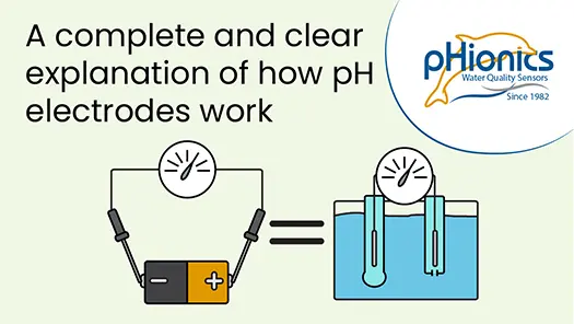
How Glass pH Electrodes Work
In this video, learn about the electrochemistry that allows silver/silver chloride pH electrodes to measure the acidity of solutions. Modern electrode design is also reviewed to demonstrate what improvements have been made and what weaknesses are still present. Click...
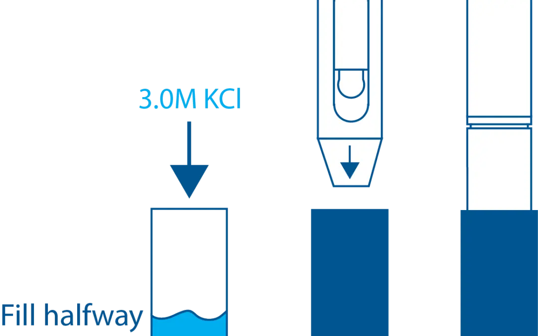
STs Series Sensor Storage
STs Series sensors are constructed from high-quality, durable materials that can be stored for long periods of time. The only weak point is the electrode, which can be damaged or expire during storage in the wrong conditions. These conditions vary depending on the type of electrode, which is why we have different storage instructions for each sensor.
How a Glass pH Electrode Works
A comprehensive article covering how glass electrodes measure pH in a simple, understandable format. Specifically for silver/silver chloride electrodes.